Photo shows lightning protection / ground wiring on omni-directional fire alarm radio transmitter antenna. Deterioration under high UV exposure may be the cause.


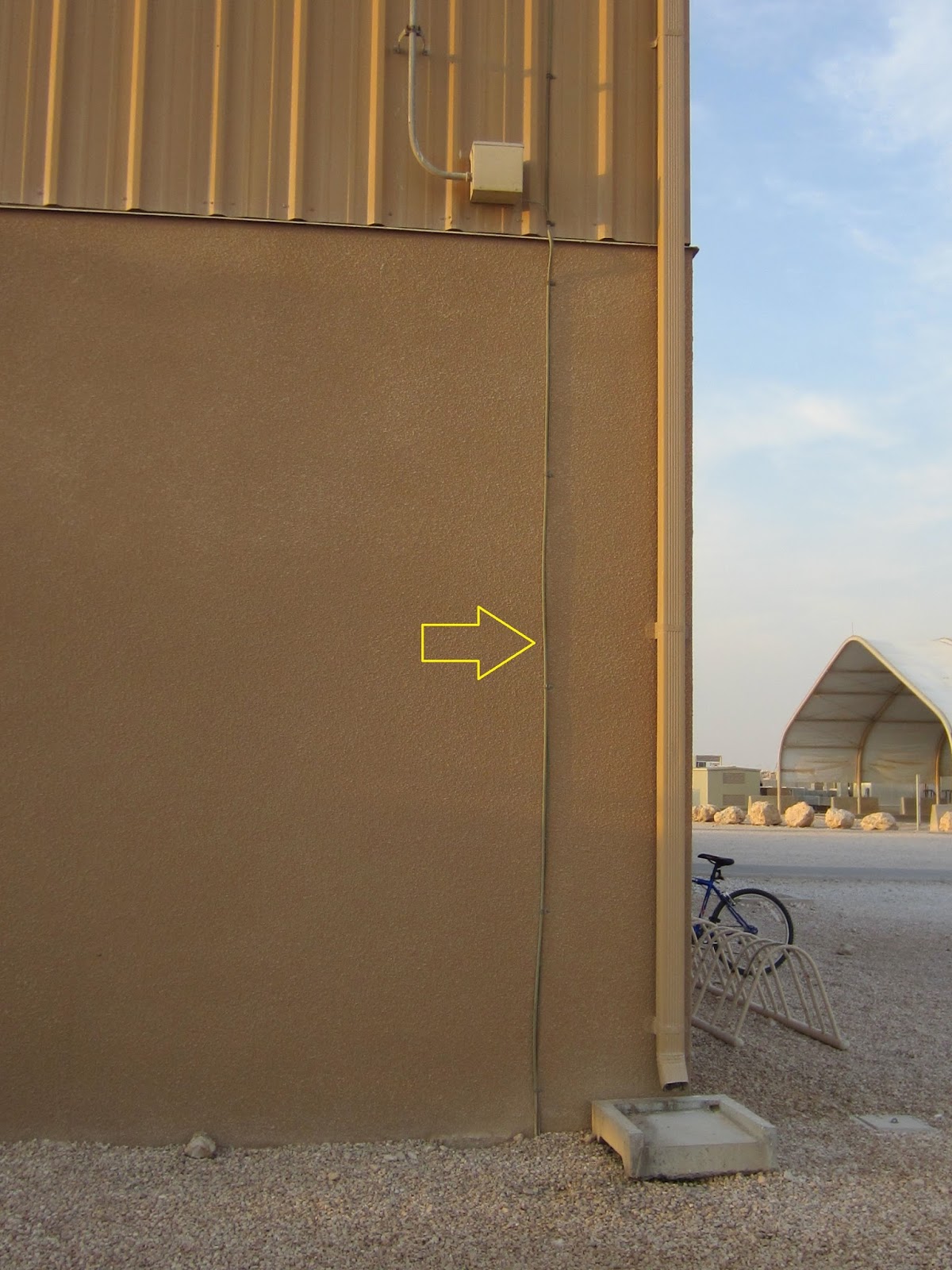
Next photo shows another fire alarm radio antenna install, ground wire is indicated with arrow. Junction box for antenna coax and connectors is visible, antenna is not.
Below, arrow points to lightning protection ground wire on top of fire department roof.

Below is photographed a damaged spade lug for a A/C 120V connection on a fire alarm system.

Photo below shows a RF omnidirectional antenna for fire alarm central service.

The following photograph shows a conventional fire alarm system and its central station radio transmitter being tested:

The photo below is of a section of programming for a fire alarm system. The programming indicates that loss of AC power will not generate a trouble condition for 6 hours.

The following configuration of fire alarm and initiating device is an unlisted configuration:

An open "LB" on fire alarm:

Drilled out FACP plexi-glass by client, so client could silence panel without unlocked FACP cabinet door. Mid-East 2017


Unlisted VHF Radio Transmitter used on Fire alarm system. Military installation, April 2017


Unlisted VHF Transmitter. Velcro used to attach radio inside cabinet. Note quality of install, with instruction sheet partially destroyed.


More Velcro:

Fire alarm control panel, Kuwait

Damage lock on FACP cabinet, military installation:


No comments:
Post a Comment