Below a photo shows a CO-2 high pressure switch main/reserve switch in the reserve position. The reason is unknown.


Another CO-2 system with reserve switch engaged:

Below a photo of a CO-2 releasing pull station. Notice the contradictory signage:

Below, a photo shows a LED indicating a CO-2 system in maintenance mode:

The following photo shows a diesel generator room protected by a zoned CO-2 system. The fire door is incorrectly propped open.

Below, the exterior of an electronics cabinet for a satellite earth station is shown. An exterior heat exhaust louver is shown. Often these do not close on CO-2 (or other clean agent activation):

On test of a clean agent (FE-13) system the louver pictured below did not close:

Another louver in the same protected cabinet/space:
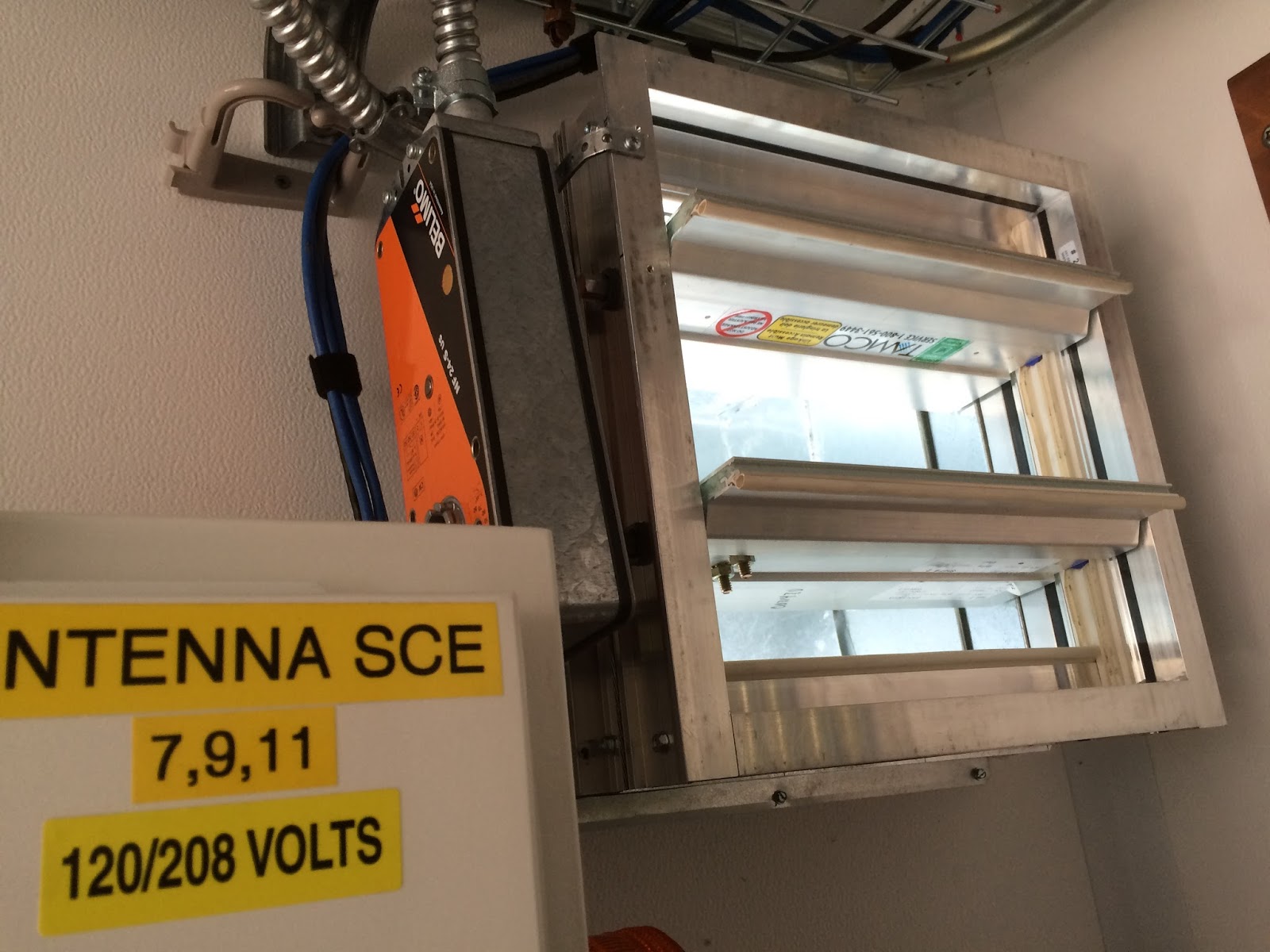
The next photo shows a motorized louver in a CO2 protected satellite earth station, the louver did not close on system activation:

The following photo shows the relay inside the releasing panel that controls the above mentioned louver:

Not all systems have electrical maintenance switches. Photographed below is a maintenance switch on a clean agent system. The maintenance switch is in the armed position:

The following photograph shows two (2) CO-2 control modules removed for testing. Note, the control modules are not supervised:

The following photo shows a CO-2 Kidde-Fenwal control module solenoid activated (from testing):
a 

The photo below shows two (2) CO-2 cylinders. They were last weighted in 2014. The photo was taken in Spring 2016:

The following shows a door on a CO-2 protected space (diesel generator, not pictured). This inspector is unaware if calculations and/or a fan test was performed to verify the door leakage will not adversely affect the CO-2 system's performance:

Photographed below ("blue box") is a CO-2 protected diesel generator. A cross-zoned fire alarm & releasing system is also installed. Central station service is provided by a 1W VHF radio network, the F/A radio antenna (to the upper right of the door) can be seen on the front of the blue conex box:

Photographed below is a diesel generator protected by a single bottle high pressure cross-zoned CO-2 system.

The photo below shows the diesel fuel shut off solenoid and ball valve that should be activated on a cross-zone fire detection signal. Note the ball valve handle is partially obstructed by the piping:

A close up of the diesel fuel shut off valve is below. Note the handle/pipe mechanical interference.

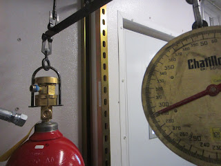
The photo below shows a high pressure CO-2 bottle about to get weighed:

Photograph below shows the above bottle's gross weight being measured:

Photo below shows a fractured CO-2 discharge indicator. Note the other indicator in the distance.

The following photo shows a CO-2 rack. Arrow points to a nut nit fully tightened:

We offer comprehensive fire door inspection services to ensure your building's fire safety compliance. Our certified inspectors assess the condition and functionality of fire doors, checking for proper installation, wear and tear, sealing, and overall performance. We focus on identifying potential risks, such as gaps, faulty hardware, or damaged seals, that could compromise the door’s ability to contain fire and smoke. Regular inspections help prevent costly fines and enhance occupant safety. We provide detailed reports with recommendations for repairs or replacements, ensuring your fire doors meet legal standards and provide optimal protection. If you're interested in learning more about fire door surveys, we invite you to visit this page where you'll find a wealth of resources, including articles, guides, and case studies.
ReplyDelete